This post is an answer to a question I got on a boating forum that I belong to. It is much too long to politely post on that forum. So I’m sticking it here. I hope it makes sense to people that can use the information.
> Yeah, the shape will definitely be more of a fair foil.
Well, first, let me emphasize it any time I post anything, that all I can promise you is that I mean well. I’m extremely capable of making mistakes. Not explaining things clearly. Not understanding things correctly, and quite clearly telling someone to do the wrong thing, because I think at that moment that is the right thing, etc. In other words I am certainly extremely fallible. So, all things are just considered to be suggestions, and I leave it up to you to double check the work and make sure that it is a good idea.
Any rudder on an Ingrid design boat is fairly large. Because of that, and the various forces that can be combined, especially in heroic situations, which people’s lives might depend on. So, I certainly suggest that you make sure that the rudder is very strong. This is the whole system from the end of the tiller to the bottom of the rudder. And any self steering device that you may use. You must decide some maximum amount of force that be rudder will be designed to carry, and then make sure that any weak links in the system are capable of handling at least that much force. Exactly how much is for you to decide. I would suggest that needs to be capable of handling the torque of several hundred pounds applied to the end of the tiller because I would estimate that I’ve seen at least a couple of hundred pounds force applied when she’s hit by a wave and the like.
Our tiller is a very nice piece of oak, but I’m told that ash would’ve been better as it is also very strong and resilient and is not dark and is easily under the varnish when there’s a problem with the varnish. We epoxied it with a clear epoxy, to protect the wood. We then put on a UV inhibited varnish to protect the epoxy. Whenever we are not using the tiller we cover it with an opaque waterproof, condom like, cover.
It’s impossible to make anything indestructible. You must find a balance. Once when we were docking, one of the line handlers made a mistake and the stern of the boat, actually the rudder, hit the pontoon at an angle and the resulting torque cracked one of our three-quarter inch plywood cheek plates. Those plates are now made of Marcarta which has about the strength of mild steel.
But, as you are aware, if we were to hit a dock again in a similar manner, it might just break somewhere else. Like at the propeller aperture.
We built the rudder using a high density polyurethane foam that we bought from a company in Tacoma in 1975. I don’t think it was the right choice, but it was better than the Styrofoam or the like, because it is quite strong. But, Airex and Kledgecel are very tough and bend quite a bit before they break. This means that they will pop back after being exposed to forces that would probably break the foam that we chose.
Our rudder has been through a lot. I’m not particularly worried about it. I’m certainly not planning to make a new one. But, I don’t think we made the best choice on our foam. When I looked around the Internet a few months ago to find some boatbuilding foam, I could not find any small quantities of foam. It looked like I had to order enough to build a whole boat with before they would talk to me. But you’re in Port Townsend, so hopefully someone there or on the Internet or somewhere else will have an answer for you.
As far as the ballast in a foam rudder is concerned, it is sort of simple and sort of complicated. Please forgive me if I’m talking down to you. I’m just trying to explain it well enough the first time and if I don’t accomplish that, let me know.
I assume that you can visualize that if the entire rudder were extremely light and mounted on the stern of the boat in the water, that the buoyancy of the submerged portion of the rudder would cause it to float up to one side or the other. I assume that this would get worse if the boat were healed over to one side.
A simple solution would be to make the entire rudder extremely heavy so that it does not do that. It is not unknown to have rudders that will sink if they are detached from the boat. However, I think this is not a good idea and it is certainly not necessary.
Clearly, the rudder pivots about the pintles and gudgeons. Also clearly, if you have a rudder that tries to float up to one side, you need to add some weight to it. The tricky part is that the further away from the pivot you apply the weight, the more effective it is. The more efficient it is. The lighter the resulting rudder is in total. So, I think it is a given, that you want to try to put the weight is far away from the pivot line as practical. That way you can use much less weight. This makes the rudder much easier to handle. Makes the pivots work much more easily. And so on.
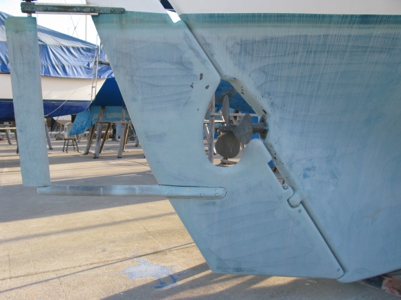
We put the weight inside the trailing edge of the rudder because we had not built the self steering gear yet. I think that it is in the lower aft corner of the foan, but not too close to the afte edge, because the edge is thin. About 1/4″ thick at the edge. Our excellent self steering gear has a long strut protruding out from the low part of the rudder, and it seems like, the very most efficient thing would’ve been to put the weight near the end of that strut. Unless of course you think you might want to remove the strut it sometime in the future. Then you would need to have the weight in the rudder as ours is.
My best recollection of the way that Mike did this is that he visualize the rudder, with the boat laying on its side and the mast horizontal. He calculated the total weight of the finished rudder and tiller and estimated how much torque it would produce if the boat were on its side with the mast horizontal.
He then estimated the buoyancy of the part of the rudder that would normally be submerged when the boat is upright and sailing and calculated how much torque that would produce.
He then added some weight, a lead bar enclosed totally inside the rudder, as far away from that pivot as practical. This was to balance the equation. So that the total estimated weight of the complete rudder, including the lead weight, would exert slightly more torque in the down direction, than the buoyancy would in the up direction.
With your fancy CNC machine and computer program, it’s entirely possible that these calculations are extremely easy to do. But we did not have that and resorted to the older method of estimating by breaking the rudder into manageable size pieces mentally and calculating the weight or buoyancy of each piece and adding of everything together.
Does that make sense? You need to estimate how thick the glass and resin is at the various points of the rudder. And in areas like around the propeller aperture or near the top of the rudder, where the cross-section is not as long for an aft, we used more glass than we did in areas of the rudder that we did not think would be under such high stress.
By the way, we bought glass and resin from Bluewater boats for the original rudder. I am quite sure that they were the same glass and resin that was used to make the hull. The hull had catastrophic osmosis problems, but the rudder that we made never has had a single blister.
Actually, right this minute, if I were starting over again, I would not put the weight in the rudder. I would make the lower strut for the self steering with an empty box, near the aft end. Then I would mount the whole thing on the boat and add weight to the tip of the strut with a string until it was balanced. Then I would remove the rudder and strut and add a little bit more weight, and glass the whole thing into the box on the end of the strut. That seems to me to be the most efficient way to make it. And it does not require any math or guesswork.
We have removed our rudder from the boat in the water, several times over the years. It is much easier to do if you have a scuba tank. But it is not at all difficult to do. And it definitely floats.
In any case, you want to have a little more weight then you will need, because it is really annoying if the rudder is trying to float up when you’re healed over or something.
> I was thinking wood for durability, repair ability, and neutral buoyancy. Sapele’s pretty good for rot resistance. This shop did a rudder for the schooner Martha out of similar materials that seems to have worked pretty well.
As far as I know, all of the numerous split rudders on Ingrid’s have been caused by the wood swelling. That and the rot danger take wood off of my list of possibilities in my personal opinion. But, you are the captain of your vessel and if I am wrong you will pay for the mistake. All I can suggest is, look at all the alternatives, and take your best shot. Cross your fingers, and nature will tell you how well you did as time goes by.
Two other things that we did that I think were very good ideas. One we did not use the Bluewater cast bronze pintles and gudgeons. We had heard that they did not fit the hull very well, and had other problems.
What we did was to clean out and prepare the pockets that are cast into the stern to accept the pintles and gudgeons and when we thought they were perfect, we coated them with parting wax, and the green water-soluble release agent that looks like prune juice before you apply it. It peels off quite easily later. Just using the special mold release wax is usually good enough, but if you have some of the release agent, I think that is much safer to use over the wax. You definitely need the wax under it in my opinion. Also, it is very important that the shape of the pocket has the correct draft angle. By that I mean that something that fits it perfectly and is very strong and rigid needs to be able to slide on and off easily. Obviously if there is an indentation in the hull and you make something very strong and rigid that fills that indentation. The resulting part will be locked to the hull. It will not slide off easily.
We then laid up a thick layer of the very best glass and resin in the 3 pockets on the hull, to make a good foundation for the pivots.
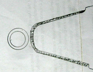
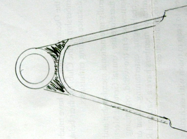
First I put glass in the bottom of the pocket.
Then I attached the tube, carefully aligned, with strong resin putty.
Then I glassed over the two parts. Then I wrapped very long glass fibers around the area shown by the vertical lines.
We used a standard PVC pipe. I do not remember for sure what size. And mounted it on a spindle horizontally so that we could wrap fiberglass cloth around it easily. We sanded it with coarse sandpaper. I think that some sources recommend that you lightly kiss it with a propane torch to break the glaze on the surface. Do some research on this because I may be quite wrong. But the idea is that you do not burn it, you just kind of give it a suntan. This is supposed to increase the adhesion of the glass and resin. You also can avoid this whole problem by buying G10 or other ready-made glass fiber tubing.
We now had a fairly thick wall, very strong fiberglass pipe, that in our case happened to have a thin PVC liner. We then cut it to 8 lengths as needed and threaded the pieces onto a long dowel or pipe that was a snug fit to get them all properly aligned. We attach that to the Stern with a short piece of tubing the right length near each of the new fiberglass gudgeons that were still attached to the hull. We then glassed them to the previous thick layer of glass in the pockets of the hull. We used a lot of glass, and arrange the direction of the fibers for maximum strength. So, we now had three very strong tubes that were in perfect alignment. Unlike the cast gudgeons.
We then took the foam core which had been shaped and mounted that foam core onto the other pieces of fiberglass tubing, with the single long straight rod through the middle of the whole mess, above and below the hull mounted gudgeons. We had cut grooves in the foam core so that the amount of glass where the glass pipes are would be substantially thicker. Much like the gudgeons on the hull. But, on the rudder there would be no visible bulge when we were done.
We now had three very strong tubes in perfect alignment temporarily attached to the hull, and five very strong tubes in perfect alignment, permanently attached, built into the rudder.
We had calculated this so that we could use 1 inch bronze pins to secure the rudder to the hull. To reduce the friction, we bought Teflon sheet 1/16 of an inch thick, and rolled it to exactly fit inside the three tubes that were attached to the hull. We also bushed the tubes in the rudder with Teflon to make the rods easy to remove and install.
We clearanced the axial dimension at all of the gudgeons so that the rudder could move up and down slightly as needed from expansion and contraction, bending, or errors in measurement. We then made four Teflon washers and put two of them below and two of them above the middle gudgeon on the hull. This is our thrust bearing for vertical load in either direction. I think it is important to only have one thrust bearing, because if you have more than one, they are pretty much guaranteed to be fighting each other.
The one inch diameter bronze pins are held in place to the rudder by a quarter inch or 5/16 inch bronze bolt, that runs athwart ships near the end of the bronze rod. The rod protrudes a little bit one end, and has been axially tapped (female threads to accept a bolt if needed) on the end to accept a bolt if you need to extract it with some force. The protruding end is also knurled, and normally you just remove the cross bolt and it quite easily slides out by grabbing the knurled portion.
In order to be able to remove it, you do need to leave a gap in the adjacent part of the rudder on the middle and upper gudgeon. The bottom one can just have the rod slide out the bottom. I will try to post some helpful photos over the next few days.
We then remove the glassed gudgeons from the hull and cleaned everything up. We finished the rudder completely. And we then reinstalled the hull gudgeons to the rudder with the bronze rods. We then used Lifeseal, to bed the hull gudgeons to the hull, and bolted them securely with silicone bronze bolts.
We used silicone bronze rods for the 1 inch hinge rods and also for the cross bolts and nuts. Because everything is theoretically exactly the same alloy and basically the 1 inch bronze hinge pin is the main element. We have not found it necessary to use zincs on them. Since our launch in 1976 there has only been a tiny bit of corrosion on the nuts on the cross pins. No corrosion at all on the one inch pins. We replace the nuts every 15 years or so, even though they are still doing a good job. It is just that they get a little rounded on the edges.
We left the cross pins full diameter except threaded them slightly at each end to accept the nuts. That way we have full bearing strength for the internal parts of these studs. I think that is superior to using a bolt in this application.
The rudder is so light and the bearings are such low friction and well aligned that when you are hauled out of the water, it is a good idea to lash the tiller because a slight breeze will cause the rudder to swing this way and that. The low friction makes the self steering gear much more effective.
Time to renew the sealant after about 10 years. 
The middle gudgeon and thrust bearings.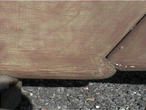 The bottom, obviously. The pin can drop out the bottom/
The cheek plates could be an interval part of the rudder. But we chose to do a more traditional look. It has the advantage that you can remove them and redesign them without having to chop up the rudder.

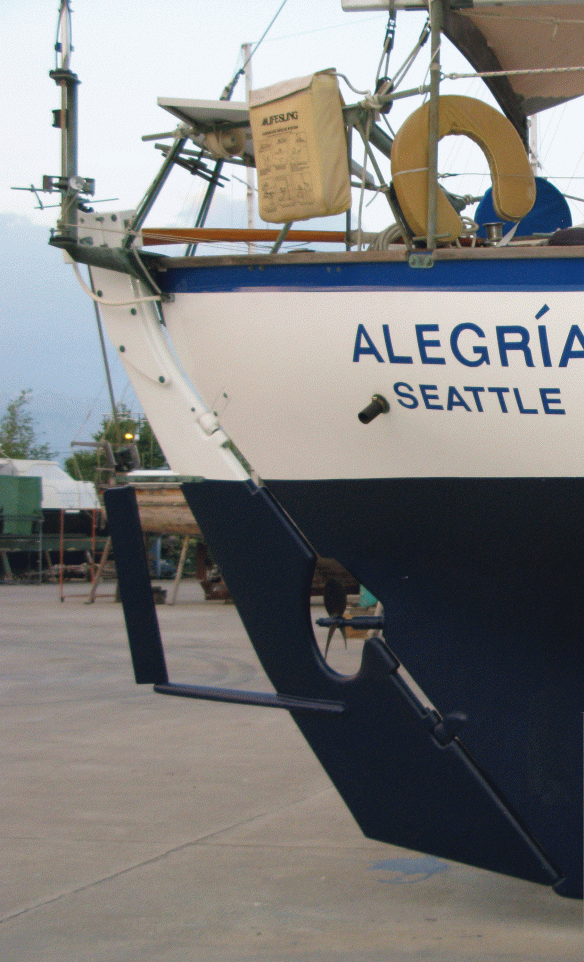 The struts are horizontal, but the tiller is lashed to the Stb side, so the rudder is angled away from the camera.
Also, I think that a clever idea that we had is to make Teflon studs that we can use to cast very precise holes in the rudder or anything that we have to drill a hole through. What we did was to find Teflon tubing and then we’d determined what size drill bit needed to be pushed into the inside of the tubing to make the outside diameter of the Teflon slightly larger than nominal Imperial sizes. Then, we bought pieces of blank drill rod. This is just very accurate diameter steel. Probably ground to a precise diameter. It is available in all the sizes imperial and metric that you can buy drill bits.
So, we ended up with a variety of lengths of steel rod, that are each covered with a thick coating of Teflon. The Teflon is exactly the size we want it to be.
In the example of mounting the cheek plates on the rudder. You very carefully layout where you want the bolts to be an drill all the way through the total assembly. Using great care to come out at the correct place on the other cheek plate. (I think that we clamped the cheek plates together and drilled the bolt holes. Then mounted the plates on the top of the rudder and drilled in from each side, halfway through. Then we cleaned up the holes.) In our case, you then remove the Micarta cheek plates, and using the technique that is described by the WEST system and others, you use a small L-shaped bit in a drill motor, that goes in and removes a slightly larger diameter, but very uniform, hole through the foam, than the hole through the fiberglass. You make the hole through the fiberglass exactly the size of the Teflon rod. You then insert the Teflon rod, from the bottom, almost to the top of the hole. You then make a very strong, fiber filled epoxy, that is still pourable and you fill the gap between the Teflon rod and the now larger hole in the foam. When it is totally full. No air bubbles or anything. You push the Teflon rod up a little bit so that it protrudes at the top and aligns.
You now let the epoxy cure, and when it is hard you push out the Teflon rod. You now have a perfectly formed epoxy tube lining the hole, which gives you much improve strength at that point. Both in compression and sideways. And it reduces but probably does not eliminate the possibility of moisture getting into the foam.
The beauty of the system is that with a good quality close cell foam, it is not important if a little moisture gets in. Work hard to not let it get in, but in theory it will not hurt anything at all.
When installing a fastener through a wooden bulkhead or the like, we can make an oversized hole, but usually we do not make it very much oversize. We then coat the inside of the wood with epoxy, over and over and over again. When we believe that we have saturated the wood, and the epoxy is starting to get gelled, we then insert the appropriate size Teflon rod to make a smooth hole and the make sure that it is the right diameter and aligned with the mating part. We hope that this will keep moisture from getting into the wood. But we still use the very best bedding compound. We have had very good luck with the BoatLife products, Lifeseal and Lifecaulk. They do take a long time to cure. And they do not seem to move through the chandleries very quickly. We have bought tubes at the chandleries, that when we get home we discovered that it is already gone off in the tube. The second time that happened we vowed to never buy it from the chandlery again. We always buy it direct from the manufacturer and have not had that problem since.
Please tell me what I have forgotten to mention, and also any mistakes or improvements that you find. I do not dream that the above is the final answer to anything. And please point out my typos.
Just is only what is worked well for us, and my ‘state-of-the-art’ at this moment. As I said at the beginning, I except absolutely no responsibility for the accuracy of this information. It is intended as food for thought. Not as a design recipe to be followed because I said so. Please investigate all of my suggestions with your own knowledge and the help of any friends and make sure that they seem like a good idea to you.
Dave
2013

